Thin Section Bearings: the Importance of a Proper Mounting
Proper mounting is critical to the optimized performance of thin section ball bearings. The use of appropriate bearing styles, orientations, recommended fits, and correct shaft and housing geometry will help assure that the bearing will achieve its full capacity.
di Rob Roos
Thin section ball bearings have a much thinner cross-section than standard bearings of the same diameter, making them more sensitive to shaft and housing fits. Proper mounting is essential to make sure that the bearing functions as intended. There are a number of factors to consider when mounting a bearing, including bearing style and orientation; the direction and magnitude of the applied loads; allowable free play in the bearing; the maximum allowable torque; shaft and housing tolerances; operating temperature; and whether the outer or inner ring is rotating.
Radial (Type C) bearings
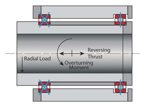
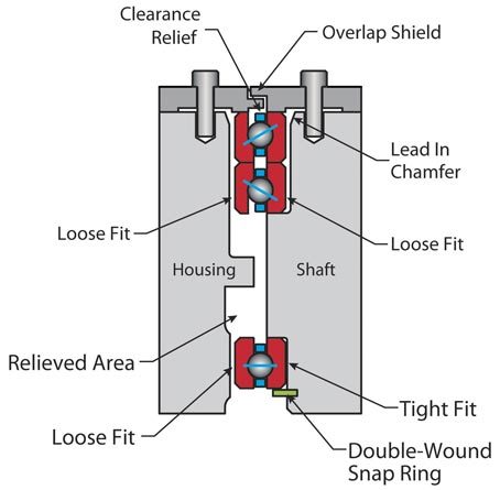
Radial bearings are typically used when the applied loads are predominantly in the radial direction. If two bearings are used on opposite ends of a long shaft, then one of the bearings should be allowed to float in the axial direction (see Figure 1). This is done so that thermal expansion of the shaft or housing does not induce a thrust force into the radial bearing.
Four-point contact (Type X) bearings
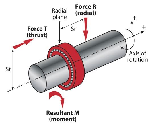
Four-point contact bearings are used when there is a thrust load or some combination of radial, thrust and moment loads (see Figure 2). If two bearings are used on the opposite ends of a long shaft, the second bearing should be a radial (Type C) bearing, and it should be allowed to float as shown in Figure 1. The use of two four-point contact bearings on the same shaft is not recommended.
A single four-point contact bearing is capable of taking a thrust load in both directions. It is also capable of taking radial and moment loads. However, this type of bearing typically has higher friction than a radial (Type C) or an angular contact (Type A) bearing of the same size. (*)
(*) With radial and four-point contact bearings, always follow the manufacturer’s recommended shaft and housing sizes, press fit, or clearance. Using the recommended fits assures that the bearings will not become radially tight after installation, which could affect bearing life and performance. Note that the recommended fits apply only to bearings with ‘standard’ clearance. They also apply to either room temperature applications or steel shafts and housings. If dissimilar metals are used, then the fits will change with temperature. This could cause the bearing to become radially tight, leading to excessive friction torque. When bearings are supplied with a diametral preload, a slight clearance is recommended for both the shaft and housing. For torque-sensitive and high-speed applications, duplex pairs of angular contact bearings are generally used in place of a single four-point contact bearing.
Angular contact (Type A) bearings
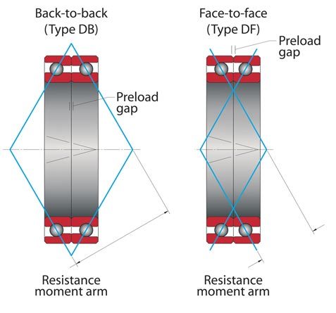
Angular contact ball bearings can take an axial (thrust) load in only one direction, and therefore are almost always used in pairs. They can be used in either a back-to-back (DB) arrangement or a face-to-face (DF) arrangement (see Figures 3 and 4). Angular contact pairs are normally used with some amount of axial preload to remove all free play and increase stiffness. Angular contact bearings may be purchased individually or as a matched set. If purchased individually, the user must set the preload during installation. If purchased as a matched set, the preload is set by the factory.
When angular contact bearings are purchased as a matched pair (called a “duplex pair”), the inner and outer rings simply need to be clamped in place as shown in Figure 5). For bearings with an axial preload, there should be a slight clearance between the bearing and both the shaft and housing. If a third bearing is used on the opposite end of a long shaft, it should be either a single radial or a face-to-face (DF) pair. It should also be free to float in the axial direction (see Figure 5). Typically, two back-to-back (DB) bearing pairs are not used on the same shaft.
General recommendations
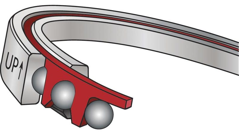
Radial and four-point contact bearings that use a “snap-over” or “crown” type ball separator should be mounted with the solid side of the separator facing up and the pocket openings facing down (if the shaft orientation is within 45° of vertical). These bearings are typically marked with an “UP” arrow to show proper orientation (see Figure 6). For horizontal shafts, there is no preferred orientation.
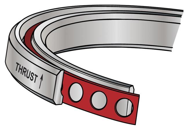
Single angular contact (Type A) bearings can only take an axial (thrust) load in one direction. The outside diameter of these bearings is marked with an arrow and the word “THRUST” to indicate the direction that a thrust load can be applied to the outer ring (see Figure 7).
When these bearings are mounted in a back-to-back (DB) arrangement, the arrows should point away from each other. In a face-to-face (DF) arrangement, the arrows should point toward each other.
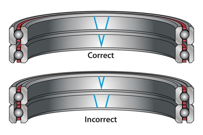
Angular contact bearings purchased as a matched (duplex) set will have a “V” marked across the O.D. and I.D. of both bearings. During installation these “V” marks should be aligned with each other. (For vertical shafts it does not matter whether the “V” is facing up or down.) The “V” marks are located at the high point of radial runout. These can be matched to the low point on the shaft and housing to reduce the assembled runout (see Figure 8).
Shaft and housing tolerances
Since their cross-sections are much thinner than standard bearings of the same diameter, thin section ball bearings are very sensitive to shaft and housing geometry. After installation, the bearing tends to take the shape of the shaft and housing, so the roundness of the shaft and housing is very important, as is the flatness of the bearing seats
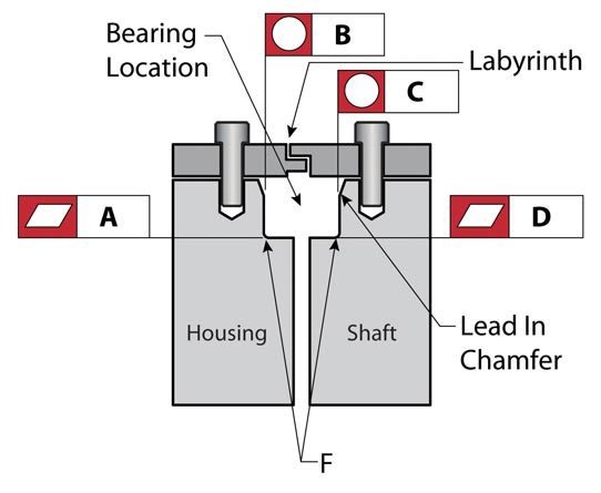
Therefore, the flatness tolerance (features A and D in Figure 9) for the bearing seats should be the same as the axial runout of the mating bearing ring. The roundness tolerance (features B and C in Figure 9) for the shaft and housing should be the same as the radial runout of the mating bearing ring.
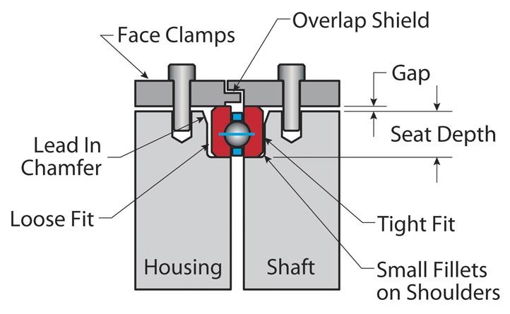
Both the shaft and the housing should have a shallow lead-in chamfer for ease of assembly. The fillet radii at the corner of the bearing seats should be smaller than the chamfer on the bearing. Where interference fits are used, heat or cold should be used to increase clearance and ease assembly. Allow the assembly to return to room temperature before tightening any fasteners. If a press fit must be used, apply uniform pressure over the entire face of the bearing. Always press on the ring with the interference fit. For example, if a press fit is used between the bearing and the shaft, then press on the inner ring, not the outer. In this case, you should never press across the races, as this can damage the bearing.
Preload
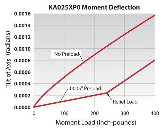
The optimal preload for any bearing depends on the application. As the preload increases, the amount of deflection under load is reduced (Figure 10) and the bearing stiffness and natural frequency increase. However, increased preload also leads to higher friction torque. Tools such as Kaydon’s free Reali-Design® software can be used to calculate the amount of deflection under an applied load for various amounts of preload. This tool can also be used to calculate the amount of preload needed for any given application.
Clamp rings
Face clamps should be used with all bearings rather than relying solely on a press fit to hold the bearing in place.
Overlapping the clamp rings to form a labyrinth shield, as shown in Figure 11, is recommended. This helps keep lubricant in the bearing and contamination out.
For bearings used in harsh environments, external seals are recommended.
To provide a uniform clamping force, a large number of small fasteners is preferable to a few large ones.
The fasteners should be tightened in a “star” pattern to evenly distribute the clamping force.
Lubrication
Open bearings are shipped with preservative oil that is not intended to be a working lubricant. Prior to installation, the bearings should be cleaned and then lubricated with an oil or grease suitable for the loads, speed, temperature, and environment.
Sealed bearings are factory-filled with a general-purpose grease. Alternative lubricants are available on request.
(Rob Roos è Senior Product Engineer, Kaydon Bearings, Muskegon, Michigan, USA)

